Stay updated with expert perspectives, custom lithium battery technology guides, downhole power innovations, and regulatory updates from our engineering team.
Choosing Smart Battery Management Systems requires more than comparing screen features or advertised battery life. The right system must match the battery chemistry, voltage range, current demand, and operating environment. A lithium pack inside a delivery vehicle faces different risks from one installed in a solar cabinet. Heat, vibration, moisture, and irregular charging can expose weak design choices quickly. This guide examines practical selection criteria used by battery engineers, system integrators, and maintenance teams. It considers cell balancing, temperature sensing, state-of-charge accuracy, state-of-health tracking, and fault protection. These functions should work together, not operate as isolated software features.
Reliable decisions also depend on evidence. Review technical datasheets, communication protocols, test records, warranty terms, and independent certification where available. Ask how the system reacts when one sensor fails, a cell becomes unbalanced, or communication is interrupted. Test those scenarios under controlled conditions. Real measurements matter. A polished dashboard cannot compensate for inaccurate voltage readings or poor thermal monitoring. Compatibility with CAN, RS-485, or cloud platforms may also affect installation cost and future maintenance. Cybersecurity deserves attention when remote access is enabled, although it is sometimes treated as an afterthought. That is a mistake. No system is perfect. Even experienced teams may misjudge energy demand or installation conditions. Recheck assumptions with recorded load data and field observations. The best choice is not always the most advanced model. It is the system that provides dependable protection, clear diagnostics, suitable integration, and measurable value throughout the battery’s working life.
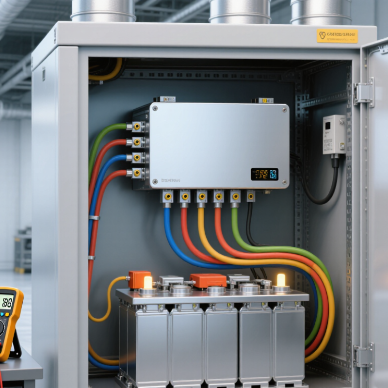
A smart battery management system does more than prevent overcharging. It continuously watches each cell’s voltage, pack current, and temperature. These measurements create the foundation for safe and reliable battery operation.
During practical testing, accurate sensing often matters more than impressive software features. The system estimates state of charge and state of health from electrical data, charging history, and temperature changes. These estimates help operators plan charging and identify aging cells. However, estimates can drift. Calibration is essential. Small errors matter.
Cell balancing is another core function. Passive balancing removes small energy differences, while active balancing can transfer energy between cells. The correct choice depends on pack size, efficiency targets, and thermal limits. A smart system also controls charging and discharging when abnormal conditions appear. It may reduce current, disconnect the pack, or trigger an alarm. Fast protection is valuable, but unnecessary shutdowns can interrupt equipment. That trade-off needs careful testing.
Communication adds practical intelligence. Through a suitable data interface, the system can report voltage trends, temperature warnings, fault records, and remaining capacity. Maintenance teams can then compare today’s readings with earlier cycles. Good systems keep clear event logs and support secure updates. Data is not truth. A damaged sensor or loose connection can mislead the entire system, so inspection and verification remain necessary. Choose functions that match the battery’s chemistry, operating environment, and service demands.
How to Choose Smart Battery Management Systems?
Identifying battery chemistry is the first technical decision. Lithium iron phosphate cells usually need different voltage limits from nickel manganese cobalt cells. Lead-acid batteries follow another charging pattern. A smart BMS must match the chemistry, cell count, and charging profile. Never choose by battery size alone. The wrong limits can reduce cycle life or create dangerous heat.
Check nominal voltage, maximum charge voltage, and minimum discharge voltage. A four-cell lithium pack may be called 12 volts, but its actual voltage changes during use. Capacity also needs careful review. A 100 Ah rating may assume a specific discharge rate and temperature. Ask whether the system supports continuous current, peak current, and balancing current. In workshop testing, I record voltage differences between cells under load. Small gaps can become serious after repeated cycling. My own early estimates were too optimistic.
Application conditions shape the final choice. An electric cart needs strong peak-current protection, while a solar storage pack may prioritize long cycle life. Cold rooms require temperature sensors and charging limits. Outdoor equipment may need sealed housing and dependable communication. Check data sheets, wiring diagrams, and fault records before installation. Test the BMS with calibrated meters, not only a phone display. Some systems report impressive data but react slowly to sudden loads. That detail is easy to miss.
A smart battery management system should make battery behavior visible, not merely prevent failure. Monitoring features should track voltage, current, temperature, state of charge, and charging history. Clear readings help technicians find weak cells before they affect the whole pack. I have found that simple dashboards often support faster decisions than crowded displays. However, sensor accuracy can decline with heat, wiring resistance, or poor placement. A system may appear intelligent while reporting incomplete information.
Protection features should respond to overvoltage, undervoltage, overcurrent, short circuits, and unsafe temperatures. Look for adjustable thresholds, fast cutoff action, and fault records that explain what happened. Balancing is equally important. Passive balancing is usually simpler, while active balancing can move energy between cells and reduce wasted charge. The right choice depends on pack size, operating conditions, and maintenance resources. Communication matters too. Interfaces such as CAN, RS-485, or wireless links can share alarms and battery data with controllers. Yet compatibility is not automatic. Test the protocol with the actual charger and control system.
Tips: Ask for sample data logs before choosing a system. Check whether readings remain stable during cold starts and heavy loads. Confirm how alerts appear, who receives them, and whether settings can be locked. Leave room for human review. Even a well-designed system can misread a damaged sensor, and that possibility deserves attention.
How to Choose Smart Battery Management Systems?
A smart battery management system should prove accuracy before adding advanced features. In field testing, compare voltage readings against a calibrated meter at low, medium, and high charge levels. Small errors can distort state-of-charge estimates and shorten battery life. BloombergNEF reported that average lithium-ion pack prices fell to 115 dollars per kWh in 2024. Lower costs increase deployment, but poor monitoring can still create expensive failures.
Safety requires more than a compliance logo. Check alignment with IEC 62619, UL 1973, and UN 38.3 requirements, depending on the battery’s application and market. Ask for test records, fault-response times, thermal-event logs, and isolation monitoring results. The IEA reported nearly 14 million electric cars were sold globally in 2023. That scale makes traceable safety evidence more important. I would not accept vague claims. A clear audit trail matters.
Tips: Test connectivity in a metal enclosure, not only in a clean laboratory. Confirm CAN, Bluetooth, or cellular data remains stable during interference. Review encryption, user permissions, and update procedures. Software support should include readable dashboards, downloadable logs, firmware rollback, and a stated support period. Also ask how the system handles sensor drift. This detail is often overlooked. My own evaluation habit is imperfect: I focus heavily on fault records and sometimes underweight installation effort. A practical pilot can expose that mistake before full deployment.
| Evaluation Dimension | Recommended Data Point | Baseline Requirement | Preferred Capability | How to Verify |
|---|---|---|---|---|
| Cell-voltage measurement accuracy | Error across the specified operating temperature range | Within ±20 mV per cell | Within ±5–10 mV per cell, with calibration data provided | Review the datasheet, calibration method, temperature range, and independent test results |
| Current measurement accuracy | Total error over the continuous and peak-current range | Within ±2% of full scale | Within ±1% of full scale or better, with drift data | Check shunt or Hall-sensor specifications, offset drift, bandwidth, and calibration procedure |
| State-of-charge estimation | Accuracy after full charge, partial cycling, aging, and temperature changes | Coulomb counting with voltage and temperature compensation | Documented error target of approximately ±5% under defined test conditions | Request test conditions, battery-model assumptions, reset behavior, and aging compensation details |
| State-of-health estimation | Capacity and resistance degradation tracking | Cycle-count and capacity-history monitoring | Model-based estimation using capacity, resistance, temperature, and cycle history | Confirm validation data for the intended cell chemistry, load profile, and operating temperature |
| Cell balancing | Balancing type, activation threshold, and balancing current | Passive balancing with configurable threshold | Passive or active balancing selected according to pack size, energy loss, and balancing time | Verify balancing current, heat dissipation, threshold, accuracy, and operation during charging |
| Protection functions | Overvoltage, undervoltage, overcurrent, short circuit, overtemperature, and undertemperature | Configurable thresholds with independent charge and discharge limits | Two-level protection, hardware cutoff path, fault latching, and event logging | Review fault-response time, hysteresis, recovery rules, and hardware/software independence |
| Safety and compliance framework | Applicable standards for the end product and battery application | Design evidence aligned with IEC 62619 where applicable | Application-specific safety process aligned with IEC 61508 or ISO 26262, when applicable, plus transport compliance under UN 38.3 | Request certificates, test reports, safety manuals, traceability records, and scope of applicability |
| Thermal monitoring | Number, location, and accuracy of temperature sensors | At least one sensor positioned near the monitored cell group | Multiple sensors covering cell groups, power electronics, and critical hot spots | Check sensor accuracy, sampling interval, placement guidance, and thermal fault response |
| Connectivity | Physical interface, protocol, data rate, and communication topology | CAN, UART, or SMBus according to the host system | Documented CAN/CAN FD or industrial Ethernet support with diagnostic services and time-stamped data | Review protocol documents, message definitions, termination requirements, and interoperability test results |
| Data logging and diagnostics | Historical data, fault records, and access permissions | Fault codes and basic operating parameters | Time-stamped logs for voltage, current, temperature, SOC, SOH, alarms, and firmware events | Confirm memory capacity, export format, clock behavior, data retention, and cybersecurity controls |
| Firmware and software support | Configuration tools, updates, diagnostics, and release management | PC configuration software with parameter backup and firmware update capability | Version-controlled releases, signed updates, rollback protection, API access, and documented change history | Evaluate software documentation, update process, compatibility policy, response times, and long-term support terms |
| Cybersecurity | Authentication, access control, secure updates, and communication protection | Password-controlled configuration access and restricted service functions | Role-based access, secure boot, signed firmware, encrypted external communication, and vulnerability response process | Request threat assessment, security architecture, update policy, and vulnerability disclosure process |
| Environmental capability | Operating temperature, humidity, vibration, shock, and enclosure protection | Rated for the temperature, vibration, and humidity conditions of the installation | Documented environmental testing with an enclosure rating such as IP65 or higher when required by the installation | Compare certified test conditions with the actual vehicle, cabinet, or outdoor installation environment |
| Scalability and serviceability | Supported series-cell count, module networking, replacement procedure, and remote service | Suitable for the required cell count with documented wiring and commissioning instructions | Modular architecture, automatic node identification, parameter backup, remote diagnostics, and controlled module replacement | Check maximum pack size, node limits, balancing coordination, spare-part policy, and commissioning time |
Note: Numerical values shown as baseline or preferred targets are procurement benchmarks rather than universal regulatory limits. The applicable requirements depend on cell chemistry, pack voltage, energy capacity, installation environment, and end-use sector. IEC 62619, IEC 61508, ISO 26262, and UN 38.3 have different scopes and should be applied only where relevant.
Choosing a smart battery management system starts with compatibility, not the feature list.
The system must match battery chemistry, voltage range, current limits, and communication protocols. A mismatch can cause inaccurate readings, unnecessary shutdowns, or unsafe charging. Check the battery datasheet and inverter requirements before comparing prices. I have seen projects fail because a connector fit physically but used the wrong communication settings.
Cost deserves a wider view.
The purchase price is only one part of ownership. Include sensors, installation, software access, testing, maintenance, and possible replacement modules. A cheaper system may require extra gateways or manual monitoring. My first budget estimate was too optimistic because I ignored commissioning time. That mistake changed how I compare quotations. Ask suppliers for documented efficiency, protection functions, warranty terms, and technical support response times. Independent test reports are useful when available.
Tips:
Leave expansion space. Select a system that supports additional batteries, channels, or monitoring points. Confirm the maximum capacity before installation. Check whether firmware updates remain available. Keep wiring and data cables clearly labeled. Test alarms under controlled conditions. Do not assume future compatibility. Record every setting. Review the design after six months, because real load patterns may differ from predictions. A flexible system can cost slightly more today, yet prevent a costly redesign later.
It monitors each cell’s voltage, pack current, and temperature. These readings reveal changes during charging and use. Small errors matter.
It estimates charge level and health from electrical readings, charging history, and temperature changes. These estimates can drift over time. Calibration remains necessary.
Balancing reduces differences between cells. Passive balancing removes small energy differences. Active balancing transfers energy between cells. The best choice depends on pack size, efficiency, and heat limits.
The system may reduce current, disconnect the pack, or trigger an alarm. It should detect excessive voltage, current, temperature, and short-circuit conditions. Fast protection helps. Unnecessary shutdowns can interrupt equipment.
A suitable data interface can report voltage trends, temperature warnings, fault records, and remaining capacity. Maintenance teams can compare current readings with earlier cycles. Clear event logs help explain failures.
Yes. A damaged sensor or loose wire can mislead the entire system. Heat, wiring resistance, and poor sensor placement may reduce accuracy. Data is not truth. Inspect and verify important readings.
Match the system with battery chemistry, voltage range, current limits, and communication settings. Also check charger and control-system requirements. A connector may fit physically but still use incorrect settings.
Include sensors, installation, software access, testing, maintenance, and replacement modules. Commissioning time can surprise your budget. My first estimate was too optimistic. That mistake deserves review.
Leave capacity for additional batteries, channels, or monitoring points. Confirm maximum capacity before installation. Check future update availability. Do not assume compatibility. Record every setting.
Choosing the right Smart Battery Management Systems begins with understanding their core purpose: monitoring battery condition, protecting cells from unsafe operation, balancing charge levels, and supporting reliable communication with external devices. Before selecting a system, users should identify the battery chemistry, operating voltage, capacity, charging requirements, and intended application. These factors determine whether the system can work safely and efficiently with the battery pack.
A careful comparison should include monitoring accuracy, overcharge and over-discharge protection, temperature control, cell balancing, communication options, and software support. It is also important to review safety standards, installation requirements, data access, and long-term reliability. The best choice should offer strong compatibility, reasonable total cost, and enough flexibility for future expansion. By evaluating both present needs and possible upgrades, users can select a Smart Battery Management Systems solution that improves battery performance, extends service life, and supports safer energy management.